Boite à décades capacitance
- Réf. HTTS
- HTS-ELEC-0057
- Réf. HTDS
- BOITE A DECADES CAPACITANCE
- Division
- Électrochimie & Tests
Galerie et schémas techniques
 Schéma

Description
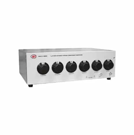
Les gammes de boites à décades de capcitances IETLabs permet de répondre à vos exigences cout/performances – Notre gamme de mesure va du sub-picoofarads au milliFards avec de très grandes précisions : – Série CS : Gamme de mesures 50 pF – 1000 µF, précisions de 0.5% à 4% -Série HACS-Z : gamme de mesure 1 pF to 11,111 µF, précision 0.05% + 0.5 pF -Série PCS : Boite à décades programmables -Série RSC : Boite à décades résistances-Capacitance [youtube id= »9a9yxfrxct0″ width= »600″ height= »340″ position= »left »]
Spécifications techniques
- EC
- Electrolytic capacitors in the 1000 μF
- RM
- Rack mounting option binding posts for 1 μF and over
- 1 pF
- 10 pF
- HIGH
- LOW
- 1 pF+
- ±0.1 pF <0.003 typical
- 1 μF
- 10 μF 50 V peak max 1 kHz <0.0007
- 10 pF
- 100 pF <0.002
- SENSE
- SENSE
- parts
- an inner shield that minimizes the low nected to the switch shaft. The outer shell of
- 10 μF
- 100 μF <0.002 polypropylene sulfi de
- <0.002
- Air Capacitors
- Models
- Total capacitance Resolution Models Total capacitance Resolution
- No. of
- No. of
- 0.1 μF
- 1 μF <0.0004
- 100 μF
- 100 Hz ±500 ppm/year
- decades
- decades
- ±0.05%
- ±200 ppm/year Sealed metallized
- 0.01 μF
- 100 nF <0.0003
- Features
- 6-decade, 1 pF through 0.1 μF
- per step
- capacitance Frequency factor
- ( Example
- 0 to 1.11111 μF, 1 pF resolution,
- 1,000 μF
- 10 mF
- Accuracy*
- Stability Max Voltage Capacitor type
- All others
- <0.0003 Hermetically sealed continuous 0-1pF parallel
- <20 ppm/°C
- Two bnc connectors labeled
- >50,000 MΩ
- connection circuit minimize
- Max Voltage
- Accuracy* Stability Capacitor type
- Inner Shield
- C
- 25 V peak max
- ±10% - - Electrolytic**
- 50 V peak max
- ±1% - Polyphenylene
- HACS-Z Series
- Page 4 of 4
- No. of Decades
- Connector Options
- HACS-Z-A-3E-1nF
- 1.11 μF 3 1 nF HACS-Z-A-6E-1nF 1,111.11 μF 6 1 nF
- HACS-Z-A-3E-1pF
- 1,110 pF 3 1 pF HACS-Z-A-6E-1pF 1.111 11 μF 6 1 pF
- HACS-Z-A-4E-1nF
- 11.11 μF 4 1 nF HACS-Z-A-8E-100pF 11,111.111 μF 8 100 pF
- HACS-Z-A-4E-1pF
- 11,110 pF 4 1 pF HACS-Z-A-7E-1nF 11,111.11 μF 7 1 nF
- HACS-Z-A-5E-1pF
- 0.111 11 μF 5 1 pF
- Capacitance/Step
- Packaging
- HACS-Z-A-3E-10nF
- 11.1 μF 3 10 nF HACS-Z-A-6E-10nF 11,111.1 μF 6 10 nF
- HACS-Z-A-3E-10pF
- 11,100 pF 3 10 pF HACS-Z-A-6E-10pF 11.111 1 μF 6 10 pF
- HACS-Z-A-3E-1μF
- 1,110 μF 3 1 μF HACS-Z-A-7E-10pF 111.111 1 μF 7 10 pF
- HACS-Z-A-4E-10nF
- 111.1 μF 4 10 nF HACS-Z-A-9E-1pF 1,111.111 11 μF 9 1 pF
- HACS-Z-A-4E-10pF
- 0.1111 μF 4 10 pF HACS-Z-A-8E-1pF 111.111 11 μF 8 1 pF
- HACS-Z-A-4E-1μF
- 11,110 μF 4 1 μF HACS-Z-A-10E-1pF 11,111.111 11 μF 10 1 pF
- HACS-Z-A-5E-10nF
- 1,111.1 μF 5 10 nF
- HACS-Z-A-5E-10pF
- 1.111 1 μF 5 10 pF
- SPECI FI CATIONS
- HIGH VALUES
- Zero capacitance
- Connection to capacitor
- HACS-Z-A-3E-100nF
- 111 μF 3 100 nF HACS-Z-A-7E-1pF 11.111 11 μF 7 1 pF
- HACS-Z-A-3E-100pF
- 111,000 pF 3 100 pF HACS-Z-A-6E-100pF 111.111 μF 6 100 pF
- HACS-Z-A-3E-10μF
- 11,100 μF 3 10 μF HACS-Z-A-7E-100pF 1, 111.111 μF 7 100 pF
- HACS-Z-A-4E-100nF
- 1,111. μF 4 100 nF HACS-Z-A-9E-10pF 11,111.111 1 μF 9 10 pF
- HACS-Z-A-4E-100pF
- 1.111 μF 4 100 pF HACS-Z-A-8E-10pF 1,111.111 1 μF 8 10 pF
- HACS-Z-A-5E-100nF
- 11,111 μF 5 100 nF Variable air-capacitor decade that attaches to the main unit for
- HACS-Z-A-5E-100pF
- 11.111 μF 5 100 pF
- • High accuracy
- 0.05%
- Storage conditions
- -40°C to 70°C frequency characteristics. To
- Operating conditions
- 10°C to 40°C inductance, and improve
- Insulation resistance
- conductors in this 4-terminal
- all dials set to zero
- construction; see below.
- 5-terminal measurement
- CURRENT, HI SENSE, LO
- all dials set to zero;
- labeled HI CURRENT, LO
- Capacitance Total decade
- Test Dissipation
- Environmental conditions
- dissipation and parasitic
- Temperature coeffi cient
- Connection to capacitor
- • Low zero capacitance
- <0.1 pF
- 1,000 pF 10 nF Position 2
- <0.0005 Mechanically stabilized
- ±(0.05%+0.5 pF) Position 1
- <0.001
- 1 to 10 1 pF to 10 μF Blank
- Standard bench top case Blank: bnc for 0.1 μF steps and under
- input capacitance and noise.
- together, the HACS-Z becomes an excellent HL
- per year to 10 kHz All others
- <0.001
- HACS-Z-A-5E-1nF 111.11 μF 5 1 nF -EC
- electrolytic capacitors in the 1,000 μF decade
- IET LABS, INC. in the GenRad Tradition
- www.ietlabs.com
- 534 Main Street, Westbury, NY 11590 TEL
- (516) 334-5959 • (800) 899-8438 • FAX: (516) 334-5988
- The shielding is divided into two different
- The outer shell of the HI connector is con- HI LO
- terminal-to-guard capacitance, and an outer
- the LO connector is connected to the outer
- ≤0.1 pF maximum capacitance obtained with
- Double-shielded
- ≤0.5 pF maximum capacitance obtained with
- Five 5-way binding posts
- shield (the case) that minimizes the detector
- case. When these two shields are connected
- 100 pF 1 nF ±(100 ppm + 0.1 pF) 500 V peak max upPosition 1
- <0.002
Applications
- Calibration d’instruments
- Tests éléctriques
Fiche produit HTTSystems
Téléchargez la fiche technique à nos couleurs et coordonnées, ou consultez-la en plein écran.
Demander un devis
La référence HTS-ELEC-0057 est reportée dans votre dossier. Vous complétez le contexte, un ingénieur reprend la suite.
Demander un devisParler à un technicien
Une question d'installation, de consommables ou de compatibilité avant de chiffrer ? Nos ingénieurs vous répondent depuis Douala.
Poser la questionÀ rapprocher de cette fiche
Même famille, ou à défaut même division.